Decorative piece built using a slow ramp-up ramp-down circuit designed around IC 555 timer.
I have been designing and building electronic circuits since I was a teenager, but they were always about function rather than form. I somehow didn’t dabble into the artistic side of circuit assembly at all these years. Last year I started following projects posted by Mohit Boite and Jiří Praus, and those inspired me to try out my hand at circuit sculptures, polish my soldering skills to go along with my discrete circuit design knowledge.
In this post, I write about my first ever attempt at circuit sculpture. I decided to replicate the Octagon LED Flower but with a twist. The original project had a LED blinking effect, which I replaced with a slow glowing variation. The design files are shared here.
Circuit Logic
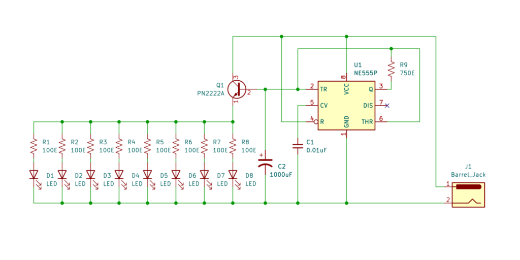
The default behavior of IC 555 in Astable Multivibrator mode (kindly refer to NE555/LM555/SE555 datasheet) is a square wave output at pin 3. But since we want a glow effect (slowly increasing/decreasing intensity cycle), we will implement a variant here.
Instead of using the VCC as charging source, and pin 7 as discharge source, we use pin 3 for both. When output is HIGH, the capacitor C2 will charge via R9. Upon reaching the 2/3 VCC threshold, the output will switch to LOW and C2 will begin discharging via the same R9 until 1/3 VCC is reached whereupon the output turns HIGH again. The cycle repeats itself at close to 50% duty cycle with time period of T = 2 * ln(2) * R9C2. In this circuit we have used R9 = 750 Ohm and C2 = 1000 microfarad, hence our time period would be approximately 1 sec.
For driving the LEDs with intensity proportional to the charge across the capacitor, we use pin 2 to drive the LEDs via a NPN BJT 2N2222A. Each Orange LED has a 100 Ohm current limiting resistor connected in series with it.
The circuit is powered by a 5V DC source via a barrel jack connector.
Assembly Steps
Step 1: Build the Octagonal LED Flower
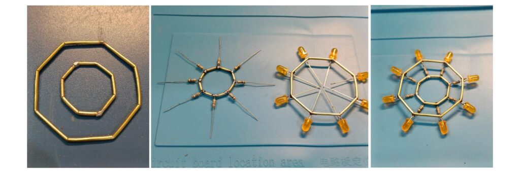
Build two octagonal rings having circumcircle of diameter 1″ and 2″ respectively using 16 SWG brass wire. Solder the 100E resistors to the smaller ring. The cathodes (-ve side) of all LEDs should be soldered to the larger ring. The outward leads of the resistors are then joined with the anodes (+ve side) of the LEDs individually.
Step 2: Build the Circuit Stem
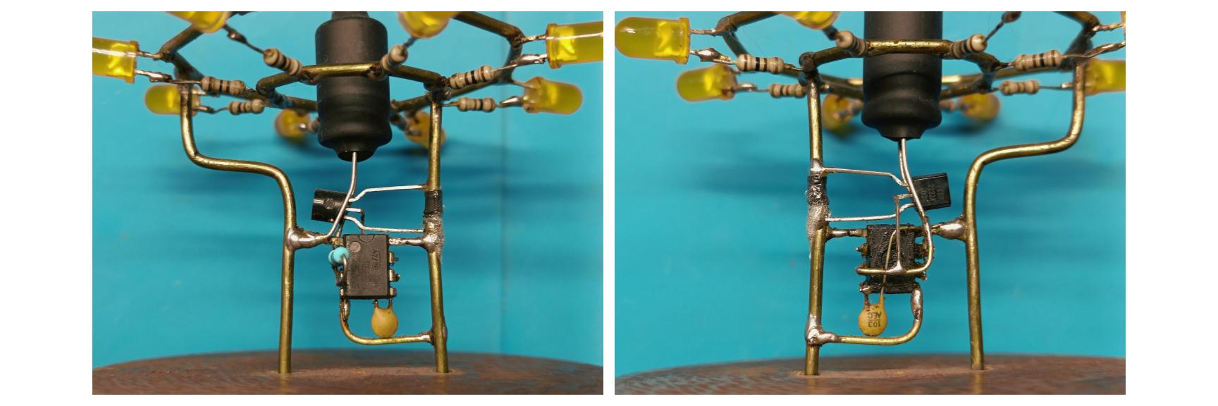
The circuit around the IC 555 is built as part of the flower stem, providing structural strength along with connections. The 1000 uF capacitor is positoned as the center of the flower and encased in heat shrunk tubing.
Step3: Build the Base
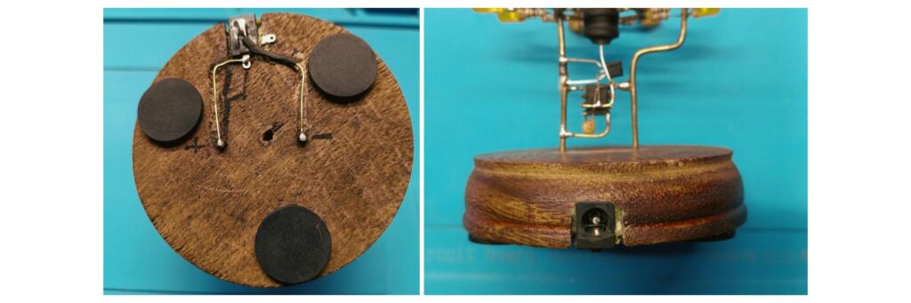
Brass wires form two sides of the stem being the +ve and -ve power rails of the circuit. It is connected to the terminals of the barrel jack embedded into the wodden base. Rubber pads are attached to the bottom of the base for soft contact. The circuit is powered by a commonly available USB charger via an USB to DC barrel jack cable.
Final Thoughts
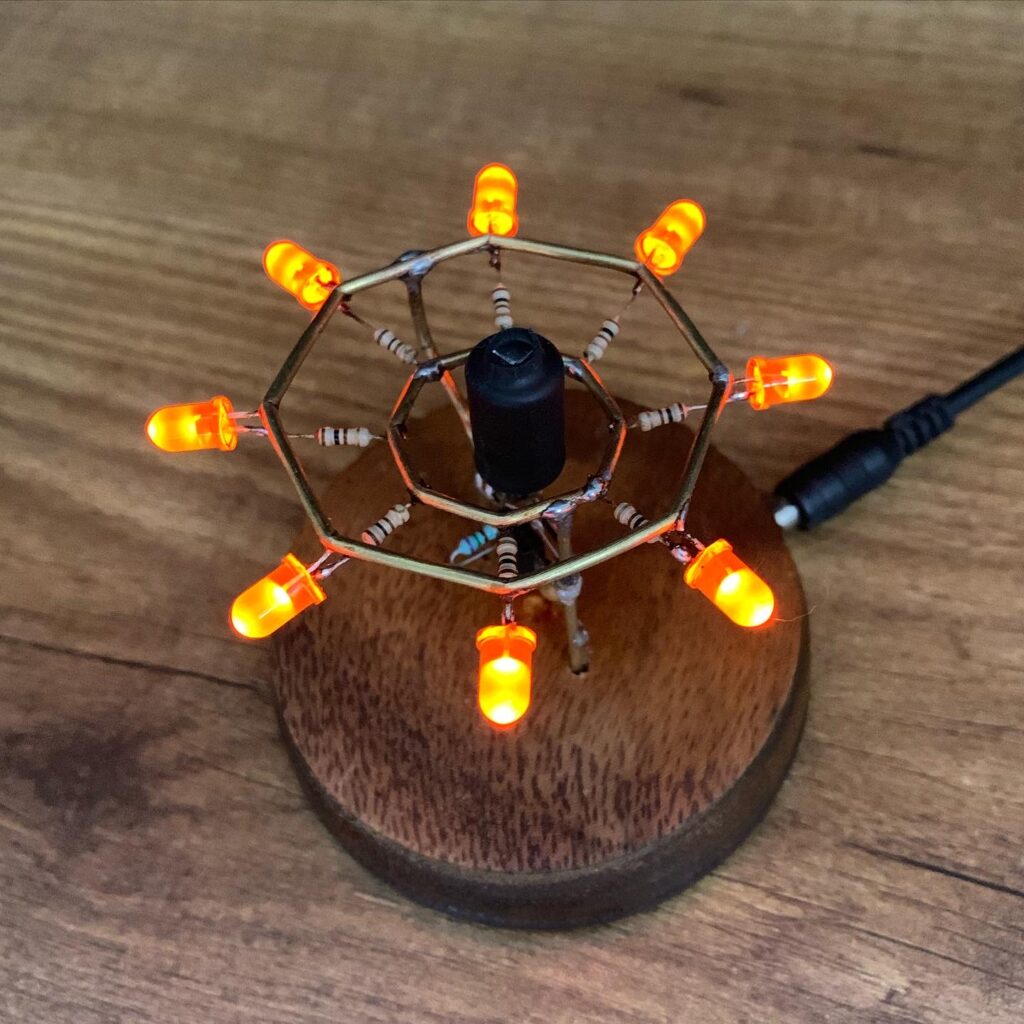
This project was done last year in Nov 2022. Being my very first circuit art piece, the finishing wasn’t top notch. Especially the octagon shapes are far from uniform and clean. My next few pieces have progressively improved in quality, which I will write about soon.
Keep watching this space for more posts on my other projects.
Great idea with innvovation