Decorative Christmas ornament built using red/green LEDs and an IC 555 timer based alternating blinker circuit.
Dec 2022: Soon after finishing the Glowing Sunflower, to hone my newly acquired skills I decided to build another piece. This one being entirely my own design from scratch, and perfect for the upcoming holiday season. The design files are shared here.
Circuit Logic
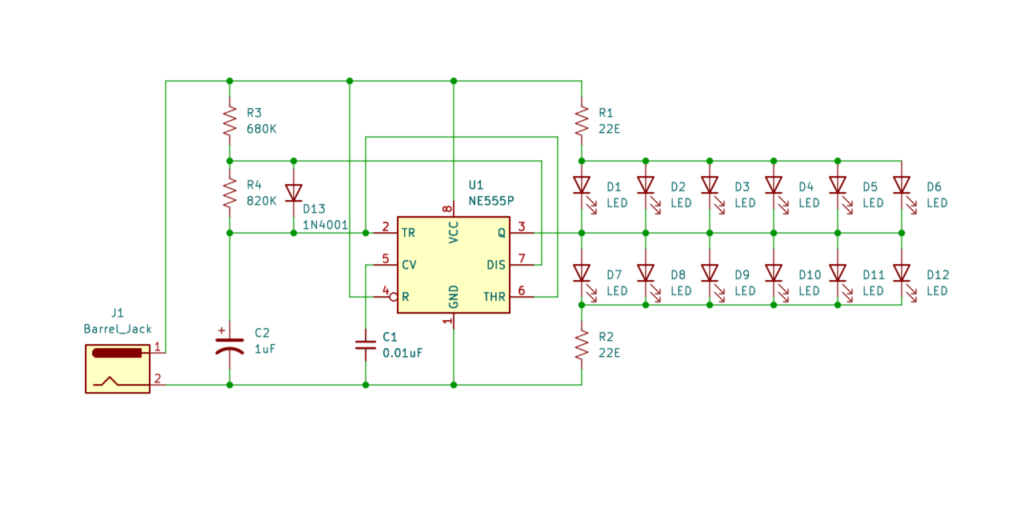
The circuit is an Astable Multivibrator designed around the IC 555 timer (kindly refer to NE555/LM555/SE555 datasheet) with square wave output at pin 3.
In the default configuration the duty cycle (ratio of output HIGH time vs LOW time) is unequal. This is due to the fact that the capacitor C2 charges via resistors R3 and R4, but discharges only via R4. To balance that out we implement a minor tweak by adding the Diode D13, which largely bypasses R4 while charging. In the resulting circuit the HIGH time tH = 0.8R3C2, and LOW time tL = 0.7R4C2. Therefore with an appropriate ratio of R3 and R4, we can get an improved performance with close to 50% duty cycle.
We use six Red LEDs as D1 thru D6, and six Green LEDs as D7 thru D12. When the output at pin 3 is HIGH, the Green LEDs light up, and when it’s LOW, the Red ones do. Note that we are directly driving the LEDs from the pin 3 of IC 555. This is possible because the maximum rated current source/sink is at 200mA. With limiting resistors R1/R2 of 22 Ohms, each LED draws approximately 25mA making the total maximum current draw at any given time at 150mA.
The circuit is powered by a 5V DC source via a barrel jack connector.
Assembly Steps
Step1: Build the six pointed star
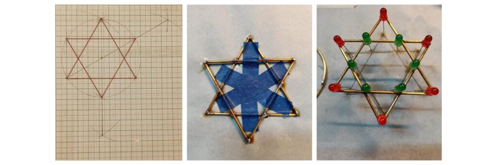
Revisiting knowledge of high school geometry, using a 6” ruler and a drawing compass, draw the template for the 6 sided star on graph paper. Each side of the equilateral triangles is set as 6.5 CM. Then trace out the shape on a tracing paper. Use masking tape to stick each length of 16 SWG hardened brass wire onto the tracing paper to hold the pieces in place for soldering the joints. Once the star is ready, solder the cathodes (-ve terminal) of Red LEDs and anodes (+ve terminal) of Green LEDs to the brass star.
Step2: Join the outer and inner rings
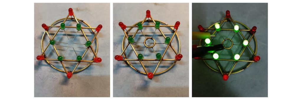
Using a wire bending tool, fashion two rings of diameter 7.5CM and 1.5CM respectively. The larger ring soldered to the anodes of the Red LEDs and the smaller one to the cathodes of the Green LEDs. Test out the finished top piece using a breadboard prototype circuit.
Step3: Free form the circuit
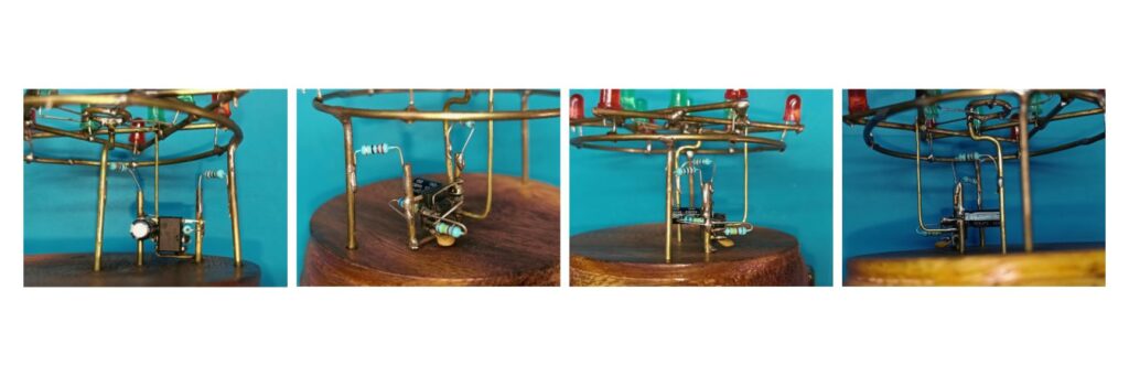
The top piece and the free form timer circuit are joined to rails of brass wires as supports aswell as means to carry current.
Step4: Base and mount
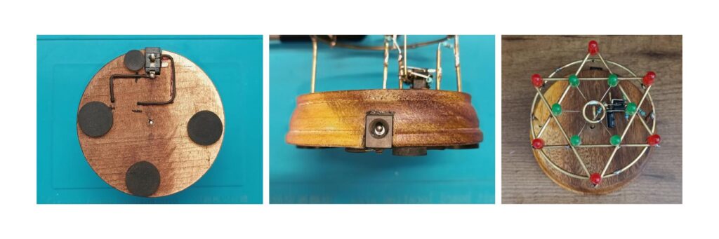
The entire piece is mounted on a circular wooden base. A DC barrel jack is embedded onto the side of the base, and its terminals are connected to the appropriate power rails of the circuit above. Rubber pads are attached to the bottom of the base for soft contact. The circuit is powered by a commonly available USB charger via an USB to DC barrel jack cable.
Next up a few wearable electronic jewelry projects. Stay tuned !